GPIO 說明
User Manual https://www.nuvoton.com/export/resource-files/UM_NuMaker-ETM-M487_User_Manual_EN_Rev1.01.pdf
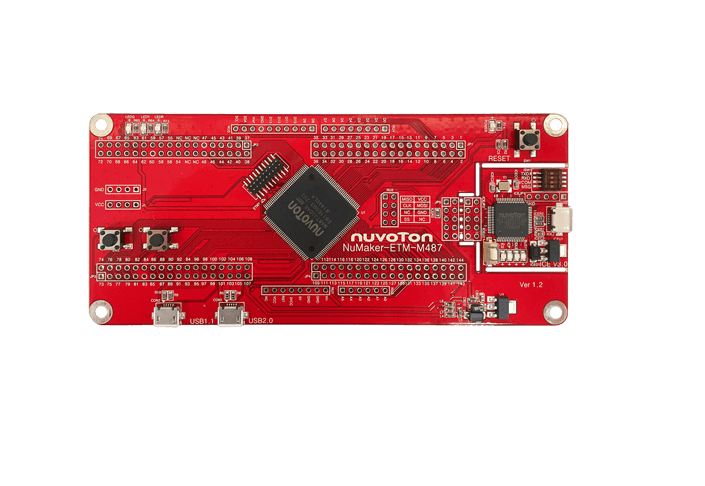
通用 I/O (GPIO) 概述
M480 系列多達118 個通用I/O管腳和其他功能管腳共享,這取決於芯片的配置。 118個管腳分配在PA, PB, PC, PD, PE, PF, PG 和 PH這8個端口上。 PA, PB, PE和PG有16個管腳,PC,PD有15個管腳,PF,PH有12個管腳。每個管腳都是獨立的,都有相應的寄存器位來控制管腳功能模式與數據。
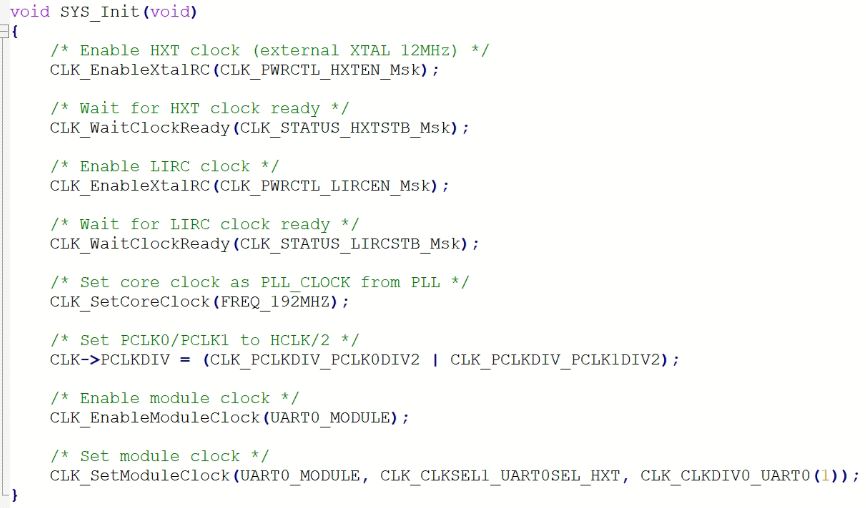
1. 設定發電廠 (clock)
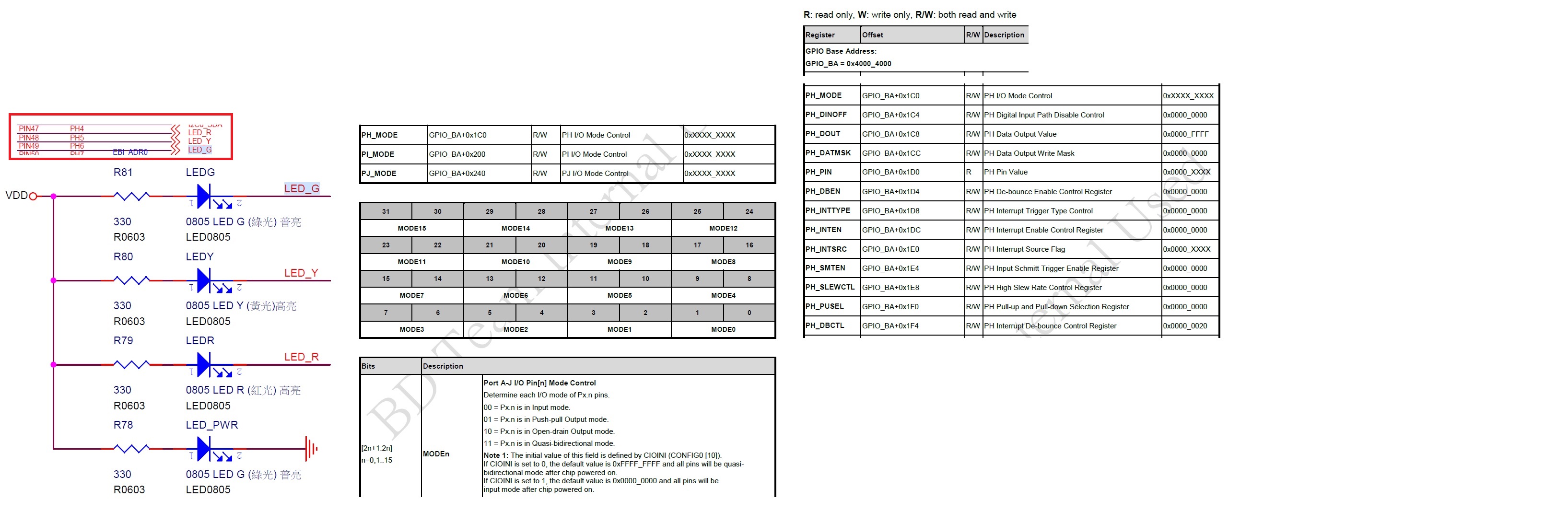
2. 設定 LED 的腳位
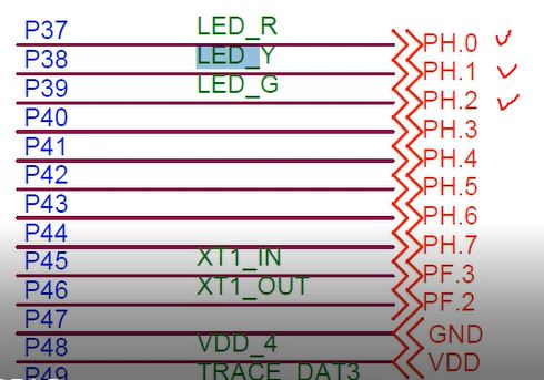
General Port 0~7 為 Low byte, 8~15 為 High byte 所以是Port H 的 0 1 2 是L,如下面黃色的標記
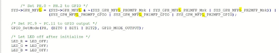
設定 Port H 0 1 2 腳位為 output

3. 設定 Button 的腳位
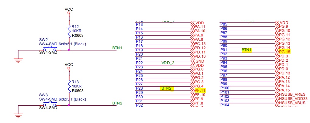
General Port 0~7 為 Low byte, 8~15 為 High byte 所以是Port B 的 15 是H , Port F 的 11 是H,如下面黃色的標記
設定 Port B 15 和 Port F 11 腳位為 input
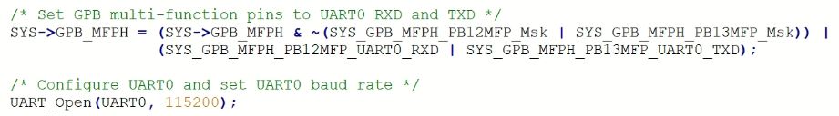
4. 設定 UART0 的腳位
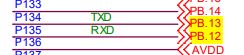
新唐大部分的M4 UART0 腳位是 PB12 RXD / PB13 TXD
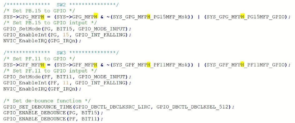
5. 設定中斷
這邊中斷就是用UART0 打印東西,和 toggle LED 的亮滅
完整程式參考
/**************************************************************************//**
* @file main.c
* @version V3.00
* @brief GPIO function for level1 training course
*
******************************************************************************/
#include <stdio.h>
#include "NuMicro.h"
#define LED_R PH0
#define LED_G PH1
#define LED_B PH2
#define LED_ON 0
#define LED_OFF 1
volatile uint32_t sw1_int_cnt = 0;
volatile uint32_t sw2_int_cnt = 0;
void SYS_Init(void)
{
/* Enable HXT clock (external XTAL 12MHz) */
CLK_EnableXtalRC(CLK_PWRCTL_HXTEN_Msk);
/* Wait for HXT clock ready */
CLK_WaitClockReady(CLK_STATUS_HXTSTB_Msk);
/* Enable LIRC clock */
CLK_EnableXtalRC(CLK_PWRCTL_LIRCEN_Msk);
/* Wait for LIRC clock ready */
CLK_WaitClockReady(CLK_STATUS_LIRCSTB_Msk);
/* Set core clock as PLL_CLOCK from PLL */
CLK_SetCoreClock(FREQ_192MHZ);
/* Set PCLK0/PCLK1 to HCLK/2 */
CLK->PCLKDIV = (CLK_PCLKDIV_PCLK0DIV2 | CLK_PCLKDIV_PCLK1DIV2);
/* Enable module clock */
CLK_EnableModuleClock(UART0_MODULE);
/* Set module clock */
CLK_SetModuleClock(UART0_MODULE, CLK_CLKSEL1_UART0SEL_HXT, CLK_CLKDIV0_UART0(1));
}
void UART0_Init()
{
/* Set GPB multi-function pins to UART0 RXD and TXD */
SYS->GPB_MFPH = (SYS->GPB_MFPH & ~(SYS_GPB_MFPH_PB12MFP_Msk | SYS_GPB_MFPH_PB13MFP_Msk)) |
(SYS_GPB_MFPH_PB12MFP_UART0_RXD | SYS_GPB_MFPH_PB13MFP_UART0_TXD);
/* Configure UART0 and set UART0 baud rate */
UART_Open(UART0, 115200);
}
void LED_Init(void)
{
/* Set PH.0 ~ PH.2 to GPIO */
SYS->GPH_MFPL = (SYS->GPH_MFPL & ~(SYS_GPH_MFPL_PH0MFP_Msk | SYS_GPH_MFPL_PH1MFP_Msk | SYS_GPH_MFPL_PH2MFP_Msk)) |
(SYS_GPH_MFPL_PH0MFP_GPIO | SYS_GPH_MFPL_PH1MFP_GPIO | SYS_GPH_MFPL_PH2MFP_GPIO);
/* Set PC.9 ~ PC.11 to GPIO output */
GPIO_SetMode(PH, (BIT0 | BIT1 | BIT2), GPIO_MODE_OUTPUT);
/* Let LED off after initialize */
LED_R = LED_OFF;
LED_G = LED_OFF;
LED_B = LED_OFF;
}
void BTN_Init(void)
{
/************** SW2 ***************/
/* Set PB.15 to GPIO */
SYS->GPG_MFPH = (SYS->GPG_MFPH & ~(SYS_GPG_MFPH_PG15MFP_Msk)) | (SYS_GPG_MFPH_PG15MFP_GPIO);
/* Set PB.15 to GPIO intput */
GPIO_SetMode(PG, BIT15, GPIO_MODE_INPUT);
GPIO_EnableInt(PG, 15, GPIO_INT_FALLING);
NVIC_EnableIRQ(GPG_IRQn);
/************** SW3 ***************/
/* Set PF.11 to GPIO */
SYS->GPF_MFPH = (SYS->GPF_MFPH & ~(SYS_GPF_MFPH_PF11MFP_Msk)) | (SYS_GPF_MFPH_PF11MFP_GPIO);
/* Set PF.11 to GPIO intput */
GPIO_SetMode(PF, BIT11, GPIO_MODE_INPUT);
GPIO_EnableInt(PF, 11, GPIO_INT_FALLING);
NVIC_EnableIRQ(GPF_IRQn);
/* Set de-bounce function */
GPIO_SET_DEBOUNCE_TIME(GPIO_DBCTL_DBCLKSRC_LIRC, GPIO_DBCTL_DBCLKSEL_512);
GPIO_ENABLE_DEBOUNCE(PG, BIT15);
GPIO_ENABLE_DEBOUNCE(PF, BIT11);
}
int main(void)
{
uint32_t sw1_cnt = 0, sw2_cnt = 0;
/* Unlock protected registers */
SYS_UnlockReg();
/* Init System, peripheral clock and multi-function I/O */
SYS_Init();
/* Lock protected registers */
SYS_LockReg();
/* Init UART0 for printf */
UART0_Init();
printf("+---------------------------------------+\n");
printf("| Level1 GPIO control Sample Code |\n");
printf("+---------------------------------------+\n\n");
/* Init LED */
LED_Init();
/* Init BTN */
BTN_Init();
while(1) {
/* Check if the SW1 is pressed */
if (sw1_int_cnt != sw1_cnt) {
sw1_cnt = sw1_int_cnt;
printf("SW1 interrupt count: %d\n", sw1_cnt);
}
/* Check if the SW2 is pressed */
if (sw2_int_cnt != sw2_cnt) {
sw2_cnt = sw2_int_cnt;
printf("SW2 interrupt count: %d\n", sw2_cnt);
}
}
}
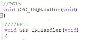
//PG15
void GPG_IRQHandler(void)
{
printf("+---------------------------------------+\n");
printf("+------------Detect PG---------------+\n");
printf("+---------------------------------------+\n");
/* Check if PG.15 the interrupt occurred */
if(GPIO_GET_INT_FLAG(PG, BIT15)) {
LED_R ^= 1;
sw1_int_cnt++;
/* Clear PG.15 interrupt flag */
GPIO_CLR_INT_FLAG(PG, BIT15);
}else {
/* Un-expected interrupt. Just clear all PB interrupts */
PG->INTSRC = PG->INTSRC;
printf("Un-expected interrupts.\n");
}
}
//PF11
void GPF_IRQHandler(void)
{
printf("+---------------------------------------+\n");
printf("+------------Detect PF---------------+\n");
printf("+---------------------------------------+\n");
/* Check if PF.11 the interrupt occurred */
if(GPIO_GET_INT_FLAG(PF, BIT11)) {
LED_G ^= 1;
sw2_int_cnt++;
/* Clear PF.11 interrupt flag */
GPIO_CLR_INT_FLAG(PF, BIT11);
} else {
/* Un-expected interrupt. Just clear all PB interrupts */
PF->INTSRC = PF->INTSRC;
printf("Un-expected interrupts.\n");
}
}
M460 的控制LED範例
/*---------------------------------------------------------------------------------------------------------*/
/*  Main Function                                                                                          */
/*---------------------------------------------------------------------------------------------------------*/
int32_t main(void)
{
    //Mode
    *(volatile unsigned int *)(0x400041C0) = 0x00001500;
    //value
    *(volatile unsigned int *)(0x400041C8) = 0x0000FF8F;

    while(1) {
        int i;
        for(i = 0; i < 50000000; i++) {} //等1下
        *(volatile unsigned int *)(0x400041C8) = 0x00000000;
		for(i = 0; i < 50000000; i++) {} //等1下
		*(volatile unsigned int *)(0x400041C8) = 0x00000070;

    }

}
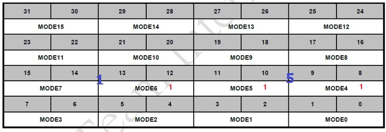
*(volatile unsigned int *)(0x400041C0) = 0x00001500;
Register 位置
0x40004000 + 0x1C0
Register的值
0x 0000 1500
000…0 1500 如下圖
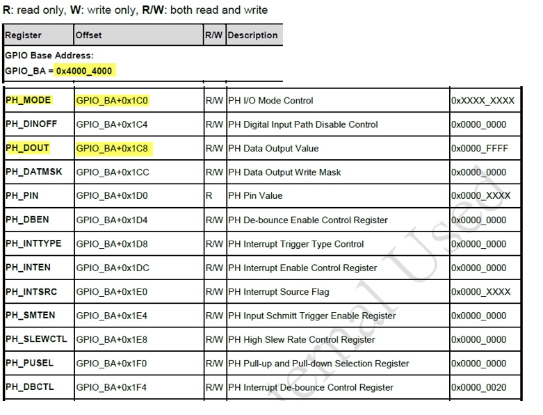
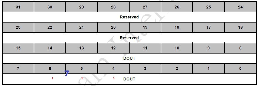
*(volatile unsigned int *)(0x400041C8) = 0x00000070;
0x1C8 是 PH_DOUT (port H out) 的控制
70 如下圖所示 (0x00000070 全滅 0x00000000 全亮)
int32_t main(void)
{


    //Mode
    *(volatile unsigned int *)(0x400041C0) = 0x00001500;
	GPIO_SetMode(PH, BIT4, GPIO_MODE_OUTPUT);
    //value
    *(volatile unsigned int *)(0x400041C8) = 0x00000000;
    GPIO_SetMode(PH, BIT4, GPIO_MODE_OUTPUT);
		PH4 = 0;
		PH5 = 0;
		PH6 = 0;


    while(1) {
        int i;
        for(i = 0; i < 50000000; i++) {} //等1百萬下
		// 全滅
        //*(volatile unsigned int *)(0x400041C8) = 0x00000000;
		PH4 = 1;
		PH5 = 1;
		PH6 = 1;
		for(i = 0; i < 50000000; i++) {} //等1百萬下
		// 全亮
		PH4 = 0;
		PH5 = 0;
		PH6 = 0;
    }

}
M460 的控制Button範例
/**************************************************************************//**
 * @file     main.c
 * @version  V3.00
 * @brief    Show the usage of GPIO interrupt function.
 *
 * @copyright SPDX-License-Identifier: Apache-2.0
 * @copyright Copyright (C) 2021 Nuvoton Technology Corp. All rights reserved.
 ******************************************************************************/

#include <stdio.h>
#include "NuMicro.h"


void GPH_IRQHandler(void);
void SYS_Init(void);
void UART0_Init(void);

/**
 * @brief       GPIO PH IRQ
 *
 * @param       None
 *
 * @return      None
 *
 * @details     The PH default IRQ, declared in startup_m460.s.
 */
void GPH_IRQHandler(void)
{
    volatile uint32_t u32temp;

    /* To check if PH.0 interrupt occurred */
    if(GPIO_GET_INT_FLAG(PH, BIT0))
    {
        GPIO_CLR_INT_FLAG(PH, BIT0);
        printf("PH.0 INT occurred.\n");
    }
		else if(GPIO_GET_INT_FLAG(PH, BIT1))
    {
        GPIO_CLR_INT_FLAG(PH, BIT1);
        printf("PH.1 INT occurred.\n");
    }
    else
    {
        /* Un-expected interrupt. Just clear all PH interrupts */
        u32temp = PH->INTSRC;
        PH->INTSRC = u32temp;
        printf("Un-expected interrupts.\n");
    }
}


void SYS_Init(void)
{

    /*---------------------------------------------------------------------------------------------------------*/
    /* Init System Clock                                                                                       */
    /*---------------------------------------------------------------------------------------------------------*/

    /* Set PCLK0 and PCLK1 to HCLK/2 */
    CLK->PCLKDIV = (CLK_PCLKDIV_APB0DIV_DIV2 | CLK_PCLKDIV_APB1DIV_DIV2);

    /* Set core clock to 200MHz */
    CLK_SetCoreClock(200000000);

    /* Enable all GPIO clock */
    CLK->AHBCLK0 |= CLK_AHBCLK0_GPACKEN_Msk | CLK_AHBCLK0_GPBCKEN_Msk | CLK_AHBCLK0_GPCCKEN_Msk | CLK_AHBCLK0_GPDCKEN_Msk |
                    CLK_AHBCLK0_GPECKEN_Msk | CLK_AHBCLK0_GPFCKEN_Msk | CLK_AHBCLK0_GPGCKEN_Msk | CLK_AHBCLK0_GPHCKEN_Msk;
    CLK->AHBCLK1 |= CLK_AHBCLK1_GPICKEN_Msk | CLK_AHBCLK1_GPJCKEN_Msk;

    /* Enable UART0 module clock */
    CLK_EnableModuleClock(UART0_MODULE);

    /* Select UART0 module clock source as HIRC and UART0 module clock divider as 1 */
    CLK_SetModuleClock(UART0_MODULE, CLK_CLKSEL1_UART0SEL_HIRC, CLK_CLKDIV0_UART0(1));

    /*---------------------------------------------------------------------------------------------------------*/
    /* Init I/O Multi-function                                                                                 */
    /*---------------------------------------------------------------------------------------------------------*/

    /* Set multi-function pins for UART0 RXD and TXD */
    SET_UART0_RXD_PB12();
    SET_UART0_TXD_PB13();
}


void UART0_Init(void)
{
    /*---------------------------------------------------------------------------------------------------------*/
    /* Init UART                                                                                               */
    /*---------------------------------------------------------------------------------------------------------*/
    /* Reset UART0 */
    SYS_ResetModule(UART0_RST);

    /* Configure UART0 and set UART0 baud rate */
    UART_Open(UART0, 115200);
}

/*---------------------------------------------------------------------------------------------------------*/
/*  Main Function                                                                                          */
/*---------------------------------------------------------------------------------------------------------*/
int32_t main(void)
{

    /* Unlock protected registers */
    SYS_UnlockReg();

    /* Init System, peripheral clock and multi-function I/O */
    SYS_Init();

    /* Lock protected registers */
    SYS_LockReg();

    /* Init UART0 for printf */
    UART0_Init();

    printf("\n\nCPU @ %d Hz\n", SystemCoreClock);
    printf("+------------------------------------------------+\n");
    printf("|    GPIO PH.0 and PH.1 Interrupt Sample Code    |\n");
    printf("+------------------------------------------------+\n\n");

    /*-----------------------------------------------------------------------------------------------------*/
    /* GPIO Interrupt Function Test                                                                        */
    /*-----------------------------------------------------------------------------------------------------*/
    printf("PH.0 and PH.1 are used to test interrupt ......\n");

    /* Configure PH.0 as Input mode and enable interrupt by rising edge trigger */
    GPIO_SetMode(PH, BIT0, GPIO_MODE_INPUT);
    GPIO_EnableInt(PH, 0, GPIO_INT_RISING);
    NVIC_EnableIRQ(GPH_IRQn);

    /* Configure PH.1 as Quasi-bidirection mode and enable interrupt by falling edge trigger */
    GPIO_SetMode(PH, BIT1, GPIO_MODE_QUASI);
    GPIO_EnableInt(PH, 1, GPIO_INT_FALLING);
    NVIC_EnableIRQ(GPH_IRQn);

    /* Enable interrupt de-bounce function and select de-bounce sampling cycle time is 1024 clocks of LIRC clock */
    GPIO_SET_DEBOUNCE_TIME(PH, GPIO_DBCTL_DBCLKSRC_LIRC, GPIO_DBCTL_DBCLKSEL_1024);
    GPIO_SET_DEBOUNCE_TIME(PH, GPIO_DBCTL_DBCLKSRC_LIRC, GPIO_DBCTL_DBCLKSEL_1024);
    GPIO_ENABLE_DEBOUNCE(PH, BIT0);
    GPIO_ENABLE_DEBOUNCE(PH, BIT1);

    /* Waiting for interrupts */
    while(1);
}