說明文件
 comments powered by Disqus
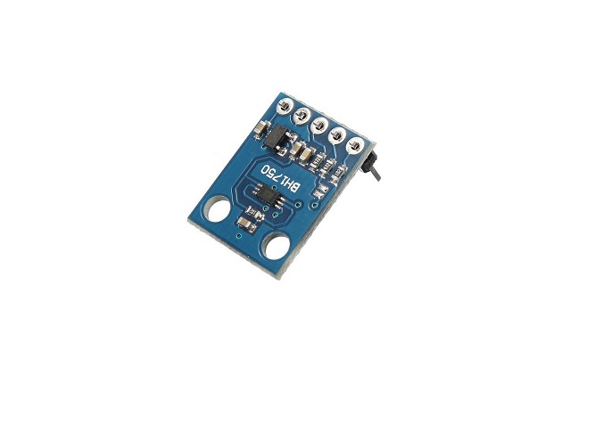
使用M460開發版的 I2C 去要 BH1750 照度計sensor的data
找M460開發版的2根空的 I2C
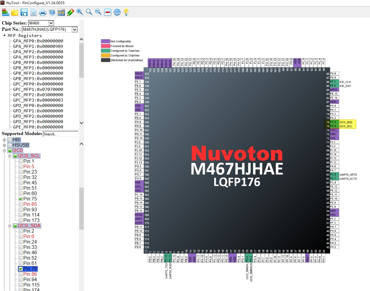
由上圖可以知道 I2C Pin角選
PA5 SCL 板上 PIN75
PA4 SDA 板上 PIN76
BSP 包 直接用 I2C_MultiBytes_Master
/* Slave address */
g_u8DeviceAddr = 0x46;
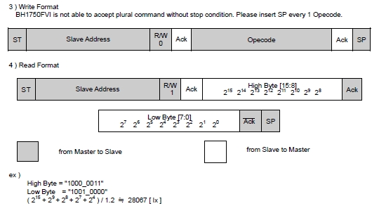
BH1750的 ID 是 0x46 (包含第8個 bit)
I2C_WriteByte(I2C0, device ID (不包含第8個bit), 要傳的命令)
I2C_WriteByte(I2C0, 0x23, 0x10);
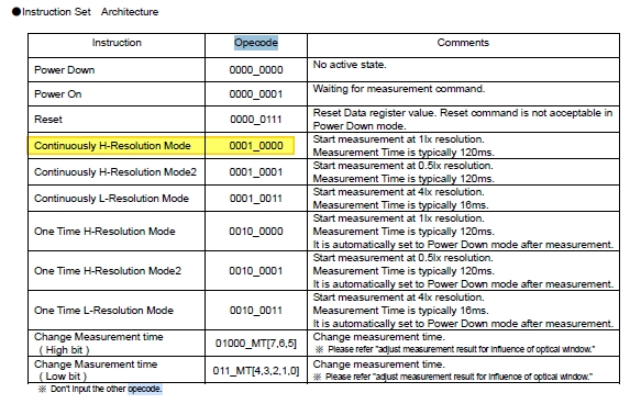
這裡命令 0x10 是參考下圖
//I2C_ReadByte(I2C0, device ID (不包含第8個bit));
//r = I2C_ReadByte(I2C0, 0x23);
讀到幾個byte = I2C_ReadMultiBytes(I2C0, device ID 不包含第8個bit, 放個陣列ReadData 會存到回到ReadData, 讀取長度len = 2 )
receive_byte = I2C_ReadMultiBytes(I2C0, 0x23, ReadData, 2);
LA 量測結果
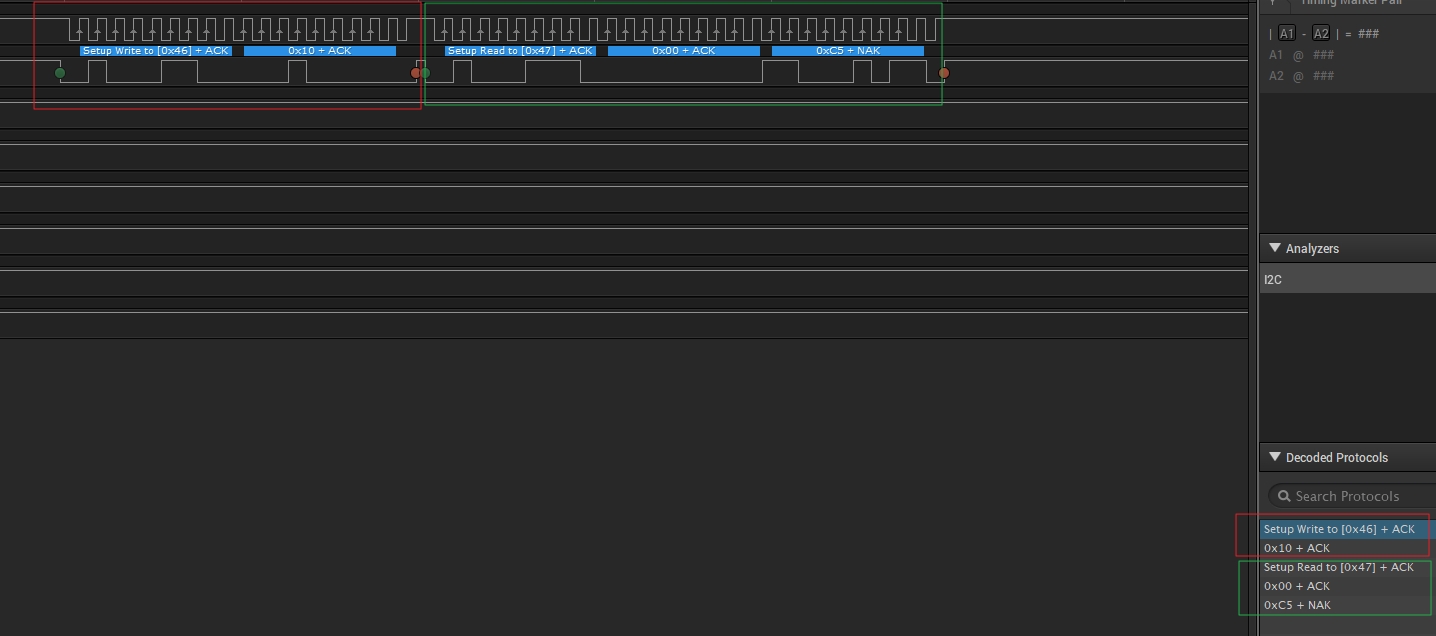
我MCU發送 0x46 (第8bit 值0 方向 write) ID ,並給值 0x10 給 Device
0x46+1 (第8bit 值1 方向 read)Device 回 MCU 2個值 : 0x00 0xC5
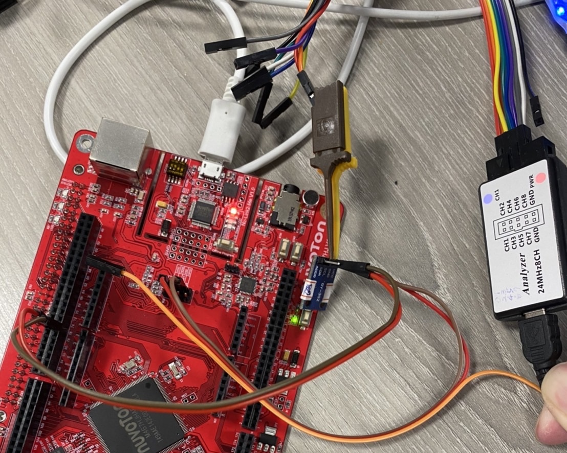
實體接線
/**************************************************************************//**
 * @file     main.c
 * @version  V3.00
 * @brief
 *           Show how to set I2C use Multi bytes API Read and Write data to Slave.
 *           Needs to work with I2C_Slave sample code.
 * @copyright (C) 2021 Nuvoton Technology Corp. All rights reserved.
 *****************************************************************************/
#include <stdio.h>
#include "NuMicro.h"

#define PLL_CLOCK       192000000

/*---------------------------------------------------------------------------------------------------------*/
/* Global variables                                                                                        */
/*---------------------------------------------------------------------------------------------------------*/
volatile uint8_t g_u8DeviceAddr;
volatile uint8_t g_au8MstTxData[3];
volatile uint8_t g_u8MstRxData;
volatile uint8_t g_u8MstDataLen;
volatile uint8_t g_u8MstEndFlag = 0;

typedef void (*I2C_FUNC)(uint32_t u32Status);
volatile static I2C_FUNC s_I2C0HandlerFn = NULL;


void SYS_Init(void)
{
    /*---------------------------------------------------------------------------------------------------------*/
    /* Init System Clock                                                                                       */
    /*---------------------------------------------------------------------------------------------------------*/

    /* Set PCLK0 and PCLK1 to HCLK/2 */
    CLK->PCLKDIV = (CLK_PCLKDIV_APB0DIV_DIV2 | CLK_PCLKDIV_APB1DIV_DIV2);

    /* Set core clock to 200MHz */
    CLK_SetCoreClock(200000000);

    /* Enable all GPIO clock */
    CLK->AHBCLK0 |= CLK_AHBCLK0_GPACKEN_Msk | CLK_AHBCLK0_GPBCKEN_Msk | CLK_AHBCLK0_GPCCKEN_Msk | CLK_AHBCLK0_GPDCKEN_Msk |
                    CLK_AHBCLK0_GPECKEN_Msk | CLK_AHBCLK0_GPFCKEN_Msk | CLK_AHBCLK0_GPGCKEN_Msk | CLK_AHBCLK0_GPHCKEN_Msk;
    CLK->AHBCLK1 |= CLK_AHBCLK1_GPICKEN_Msk | CLK_AHBCLK1_GPJCKEN_Msk;

    /* Enable UART0 module clock */
    CLK_EnableModuleClock(UART0_MODULE);

    /* Select UART0 module clock source as HIRC and UART0 module clock divider as 1 */
    CLK_SetModuleClock(UART0_MODULE, CLK_CLKSEL1_UART0SEL_HIRC, CLK_CLKDIV0_UART0(1));

    /* Enable I2C0 peripheral clock */
    CLK_EnableModuleClock(I2C0_MODULE);

    /*---------------------------------------------------------------------------------------------------------*/
    /* Init I/O Multi-function                                                                                 */
    /*---------------------------------------------------------------------------------------------------------*/

    /* Set multi-function pins for UART0 RXD and TXD */
    SET_UART0_RXD_PB12();
    SET_UART0_TXD_PB13();;

    /* Set I2C0 multi-function pins */
    SET_I2C0_SDA_PA4();
    SET_I2C0_SCL_PA5();

    /* I2C pin enable schmitt trigger */
    PA->SMTEN |= GPIO_SMTEN_SMTEN4_Msk | GPIO_SMTEN_SMTEN5_Msk;
}

void I2C0_Init(void)
{
    /* Open I2C module and set bus clock */
    I2C_Open(I2C0, 100000);

    /* Get I2C0 Bus Clock */
    printf("I2C clock %d Hz\n", I2C_GetBusClockFreq(I2C0));
}

void I2C0_Close(void)
{
    /* Disable I2C0 interrupt and clear corresponding NVIC bit */
    I2C_DisableInt(I2C0);
    NVIC_DisableIRQ(I2C0_IRQn);

    /* Disable I2C0 and close I2C0 clock */
    I2C_Close(I2C0);
    CLK_DisableModuleClock(I2C0_MODULE);

}


int32_t main(void)
{
    uint32_t receive_byte;
    uint8_t ReadData[2];
		uint32_t Lux;

    uint32_t i;
    uint8_t txbuf[256] = {0}, rDataBuf[256] = {0};

    /* Unlock protected registers */
    SYS_UnlockReg();

    /* Init System, IP clock and multi-function I/O. */
    SYS_Init();

    /* Configure UART0: 115200, 8-bit word, no parity bit, 1 stop bit. */
    UART_Open(UART0, 115200);

#ifdef _PZ
    /* For palladium */
    UART0->BAUD = UART_BAUD_MODE2 | UART_BAUD_MODE2_DIVIDER(153600, 38400);
#endif

    /*
        This sample code sets I2C bus clock to 100kHz. Then, Master accesses Slave with Multi Bytes Write
        and Multi Bytes Read operations, and check if the read data is equal to the programmed data.
    */
    printf("+--------------------------------------------------------+\n");
    printf("| I2C Driver Sample Code for Multi Bytes Read/Write Test |\n");
    printf("| Needs to work with I2C_Slave sample code               |\n");
    printf("|                                                        |\n");
    printf("| I2C Master (I2C0) <---> I2C Slave(I2C0)                |\n");
    printf("| !! This sample code requires two borads to test !!     |\n");
    printf("+--------------------------------------------------------+\n");

    printf("\n");

    /* Init I2C0 */
    I2C0_Init();

    /* Slave address */
    g_u8DeviceAddr = 0x46;


    I2C_WriteByte(I2C0, 0x23, 0x10);
    //r = I2C_ReadByte(I2C0, 0x23);
    receive_byte = I2C_ReadMultiBytes(I2C0, 0x23, ReadData, 2);
    printf("receive_byte = %d \n", receive_byte);
    printf("ReadData[0] = %x \n", ReadData[0]);
    printf("ReadData[1] = %x \n", ReadData[1]);
	Lux = ReadData[0] * 256 + ReadData[1];

    while(1)
	{
			I2C_ReadMultiBytes(I2C0, 0x23, ReadData, 2);
			Lux = ReadData[0] * 256 + ReadData[1];
			printf("Lux = %d \n", Lux);
	}

}
/*** (C) COPYRIGHT 2021 Nuvoton Technology Corp. ***/