說明文件
 comments powered by Disqus
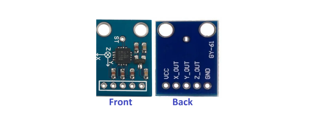
使用M460開發版的 ADC 去要 GY-61 Acc 加速度計的data

參考 Opennuvoton 的 EADC_ADINT_Trigger 範例
觀察到 user manual 的 PB0 PB1 PB2 是有接出來可以用的,所以:
/* Set multi-function pins for EADC0 channels. */
SET_EADC0_CH0_PB0();
SET_EADC0_CH1_PB1();
SET_EADC0_CH2_PB2();
看 Example Code 的 channel 0 、 channel 1 、 channel 2 要設定對
/* Configure the sample 4 module for analog input channel 0 and enable ADINT0 trigger source */
EADC_ConfigSampleModule(EADC0, 4, EADC_ADINT0_TRIGGER, 0);
/* Configure the sample 5 module for analog input channel 1 and enable ADINT0 trigger source */
EADC_ConfigSampleModule(EADC0, 5, EADC_ADINT0_TRIGGER, 1);
/* Configure the sample 6 module for analog input channel 2 and enable ADINT0 trigger source */
EADC_ConfigSampleModule(EADC0, 6, EADC_ADINT0_TRIGGER, 2);
實體接線

/**************************************************************************//**
 * @file     main.c
 * @version  V3.00
 * @brief    Use ADINT interrupt to do the EADC continuous scan conversion.
 *
 * @copyright SPDX-License-Identifier: Apache-2.0
 * @copyright Copyright (C) 2021 Nuvoton Technology Corp. All rights reserved.
 ******************************************************************************/
#include <stdio.h>
#include "NuMicro.h"


/*---------------------------------------------------------------------------------------------------------*/
/* Define global variables and constants                                                                   */
/*---------------------------------------------------------------------------------------------------------*/
static volatile uint32_t g_u32AdcIntFlag, g_u32COVNUMFlag = 0;

/*---------------------------------------------------------------------------------------------------------*/
/* Define functions prototype                                                                              */
/*---------------------------------------------------------------------------------------------------------*/
int32_t main(void);
void EADC_FunctionTest(void);
void EADC00_IRQHandler(void);
void SYS_Init(void);
void UART0_Init(void);
/*---------------------------------------------------------------------------------------------------------*/
/* EADC interrupt handler                                                                                  */
/*---------------------------------------------------------------------------------------------------------*/
void EADC00_IRQHandler(void)
{
    g_u32AdcIntFlag = 1;
    EADC_CLR_INT_FLAG(EADC0, EADC_STATUS2_ADIF0_Msk);      /* Clear the A/D ADINT0 interrupt flag */
}

void SYS_Init(void)
{

    /* Set PF multi-function pins for XT1_OUT(PF.2) and XT1_IN(PF.3) */
    SET_XT1_OUT_PF2();
    SET_XT1_IN_PF3();

    /*---------------------------------------------------------------------------------------------------------*/
    /* Init System Clock                                                                                       */
    /*---------------------------------------------------------------------------------------------------------*/

    /* Enable HIRC and HXT clock */
    CLK_EnableXtalRC(CLK_PWRCTL_HIRCEN_Msk | CLK_PWRCTL_HXTEN_Msk);

    /* Wait for HIRC and HXT clock ready */
    CLK_WaitClockReady(CLK_STATUS_HIRCSTB_Msk | CLK_STATUS_HXTSTB_Msk);

    /* Set PCLK0 and PCLK1 to HCLK/2 */
    CLK->PCLKDIV = (CLK_PCLKDIV_APB0DIV_DIV2 | CLK_PCLKDIV_APB1DIV_DIV2);

    /* Set core clock to 200MHz */
    CLK_SetCoreClock(200000000);

    /* Enable all GPIO clock */
    CLK->AHBCLK0 |= CLK_AHBCLK0_GPACKEN_Msk | CLK_AHBCLK0_GPBCKEN_Msk | CLK_AHBCLK0_GPCCKEN_Msk | CLK_AHBCLK0_GPDCKEN_Msk |
                    CLK_AHBCLK0_GPECKEN_Msk | CLK_AHBCLK0_GPFCKEN_Msk | CLK_AHBCLK0_GPGCKEN_Msk | CLK_AHBCLK0_GPHCKEN_Msk;
    CLK->AHBCLK1 |= CLK_AHBCLK1_GPICKEN_Msk | CLK_AHBCLK1_GPJCKEN_Msk;

    /* Enable UART0 module clock */
    CLK_EnableModuleClock(UART0_MODULE);

    /* Select UART0 module clock source as HIRC and UART0 module clock divider as 1 */
    CLK_SetModuleClock(UART0_MODULE, CLK_CLKSEL1_UART0SEL_HIRC, CLK_CLKDIV0_UART0(1));

    /* Enable EADC0 module clock */
    CLK_EnableModuleClock(EADC0_MODULE);

    /* Set EADC0 clock divider as 12 */
    CLK_SetModuleClock(EADC0_MODULE, CLK_CLKSEL0_EADC0SEL_PLL_DIV2, CLK_CLKDIV0_EADC0(12));

    /*---------------------------------------------------------------------------------------------------------*/
    /* Init I/O Multi-function                                                                                 */
    /*---------------------------------------------------------------------------------------------------------*/

    /* Set multi-function pins for UART0 RXD and TXD */
    SET_UART0_RXD_PB12();
    SET_UART0_TXD_PB13();

    /* Set multi-function pins for EADC0 channels. */
    SET_EADC0_CH0_PB0();
    SET_EADC0_CH1_PB1();
    SET_EADC0_CH2_PB2();


    /* Disable digital input path of EADC analog pin to prevent leakage */
    GPIO_DISABLE_DIGITAL_PATH(PB, BIT3 | BIT2 | BIT1 | BIT0);

}

void UART0_Init(void)
{
    /*---------------------------------------------------------------------------------------------------------*/
    /* Init UART                                                                                               */
    /*---------------------------------------------------------------------------------------------------------*/

    /* Configure UART0 and set UART0 baud rate */
    UART_Open(UART0, 115200);
}

/*---------------------------------------------------------------------------------------------------------*/
/* EADC function test                                                                                      */
/*---------------------------------------------------------------------------------------------------------*/
void EADC_FunctionTest(void)
{
    uint8_t  u8Option, u8SampleCnt = 0;
    int32_t  ai32ConversionData[8] = {0};
    uint32_t u32TimeOutCnt = 0;
    int32_t  i32Err;

    printf("\n");
    printf("+----------------------------------------------------------------------+\n");
    printf("|                      ADINT trigger mode test                         |\n");
    printf("+----------------------------------------------------------------------+\n");

    printf("\nIn this test, software will get conversion result from fast channels.\n");

    while(1)
    {
        printf("\n\nSelect input mode:\n");
        printf("  [1] Single end input (channel 0, 1, 2 )\n");
        printf("  Other keys: exit continuous scan mode test\n");
        u8Option = (uint8_t)getchar();
        if(u8Option == '1')
        {
            /* Set input mode as single-end and enable the A/D converter */
            i32Err = EADC_Open(EADC0, EADC_CTL_DIFFEN_SINGLE_END);

            /* Check EADC global error code. */
            if (i32Err != 0)
            {
                if (i32Err == EADC_CAL_ERR)
                {
                    printf("EADC has calibration error.\n");
                    return;
                }
                else if (i32Err == EADC_CLKDIV_ERR)
                {
                    printf("EADC clock frequency is configured error.\n");
                    return;
                }
                else
                {
                    printf("EADC has operation error.\n");
                    return;
                }
            }

            /* Configure the sample 4 module for analog input channel 10 and enable ADINT0 trigger source */
            EADC_ConfigSampleModule(EADC0, 4, EADC_ADINT0_TRIGGER, 0);
            /* Configure the sample 5 module for analog input channel 11 and enable ADINT0 trigger source */
            EADC_ConfigSampleModule(EADC0, 5, EADC_ADINT0_TRIGGER, 1);
            /* Configure the sample 6 module for analog input channel 14 and enable ADINT0 trigger source */
            EADC_ConfigSampleModule(EADC0, 6, EADC_ADINT0_TRIGGER, 2);
            ///* Configure the sample 7 module for analog input channel 15 and enable ADINT0 trigger source */
            //EADC_ConfigSampleModule(EADC0, 7, EADC_ADINT0_TRIGGER, 3);

            /* Clear the A/D ADINT0 interrupt flag for safe */
            EADC_CLR_INT_FLAG(EADC0, EADC_STATUS2_ADIF0_Msk);

            /* Enable the sample module 7 interrupt */
            EADC_ENABLE_INT(EADC0, BIT0);//Enable sample module  A/D ADINT0 interrupt.
            EADC_ENABLE_SAMPLE_MODULE_INT(EADC0, 0, BIT7);//Enable sample module 7 interrupt.
            NVIC_EnableIRQ(EADC00_IRQn);

            /* Reset the ADC indicator and trigger sample module 7 to start A/D conversion */
            g_u32AdcIntFlag = 0;
            g_u32COVNUMFlag = 0;
            EADC_START_CONV(EADC0, BIT7);

            __WFI();

            /* Disable the sample module 7 interrupt */
            EADC_DISABLE_SAMPLE_MODULE_INT(EADC0, 0, BIT7);

            /* Wait conversion done */
            u32TimeOutCnt = SystemCoreClock; /* 1 second time-out */
            while(EADC_GET_DATA_VALID_FLAG(EADC0, (BIT7 | BIT6 | BIT5 | BIT4)) != (BIT7 | BIT6 | BIT5 | BIT4))
            {
                if(--u32TimeOutCnt == 0)
                {
                    printf("Wait for EADC conversion done time-out!\n");
                    return;
                }
            }

            /* Get the conversion result of the sample module */
            for(u8SampleCnt = 0; u8SampleCnt < 4; u8SampleCnt++)
                ai32ConversionData[u8SampleCnt] = EADC_GET_CONV_DATA(EADC0, u8SampleCnt + 4);

            printf("Conversion result of channel %d: 0x%X (%d)\n", 10, ai32ConversionData[0], ai32ConversionData[0]);
            printf("Conversion result of channel %d: 0x%X (%d)\n", 11, ai32ConversionData[1], ai32ConversionData[1]);
            printf("Conversion result of channel %d: 0x%X (%d)\n", 14, ai32ConversionData[2], ai32ConversionData[2]);


        }

        else
            return ;

        /* Reset the sample module 4, 5, 6, 7 for analog input channel and disable ADINT0 trigger source */
        EADC_ConfigSampleModule(EADC0, 4, EADC_SOFTWARE_TRIGGER, 0);
        EADC_ConfigSampleModule(EADC0, 5, EADC_SOFTWARE_TRIGGER, 0);
        EADC_ConfigSampleModule(EADC0, 6, EADC_SOFTWARE_TRIGGER, 0);

        /* Clear the conversion result of the sample module */
        for(u8SampleCnt = 0; u8SampleCnt < 4; u8SampleCnt++)
            ai32ConversionData[u8SampleCnt] = 0;
    }
}


/*---------------------------------------------------------------------------------------------------------*/
/*  Main Function                                                                                          */
/*---------------------------------------------------------------------------------------------------------*/
int32_t main(void)
{

    /* Unlock protected registers */
    SYS_UnlockReg();

    /* Init System, IP clock and multi-function I/O */
    SYS_Init();

    /* Lock protected registers */
    SYS_LockReg();

    /* Init UART0 for printf */
    UART0_Init();

    /*---------------------------------------------------------------------------------------------------------*/
    /* SAMPLE CODE                                                                                             */
    /*---------------------------------------------------------------------------------------------------------*/

    printf("\nSystem clock rate: %d Hz", SystemCoreClock);

    /* EADC function test */
    EADC_FunctionTest();

    /* Reset EADC module */
    SYS_ResetModule(EADC0_RST);

    /* Disable EADC IP clock */
    CLK_DisableModuleClock(EADC0_MODULE);

    /* Disable External Interrupt */
    NVIC_DisableIRQ(EADC00_IRQn);

    printf("Exit EADC sample code\n");

    while(1);

}


/*** (C) COPYRIGHT 2021 Nuvoton Technology Corp. ***/