說明文件
 comments powered by Disqus
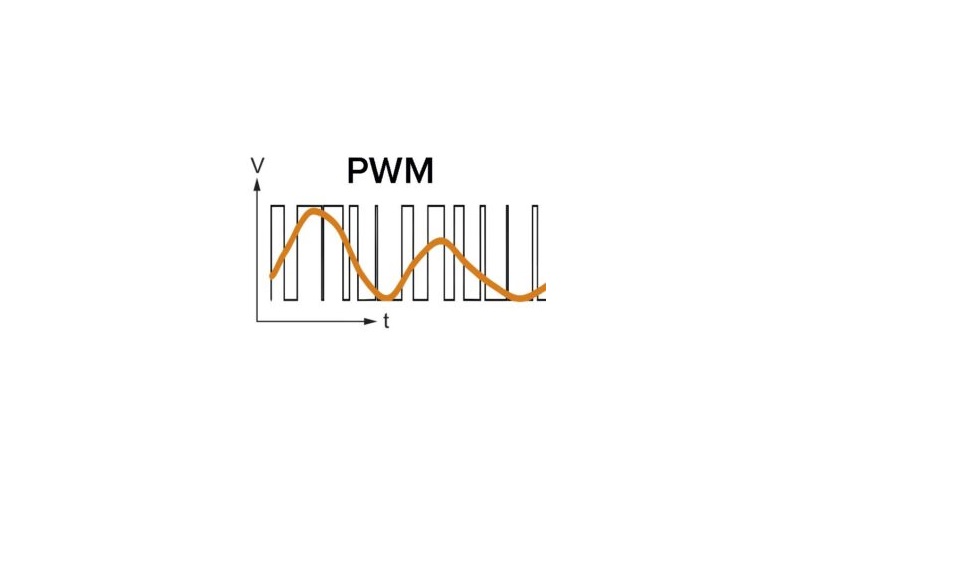
PWM 的 應用範例
BSP EPWM
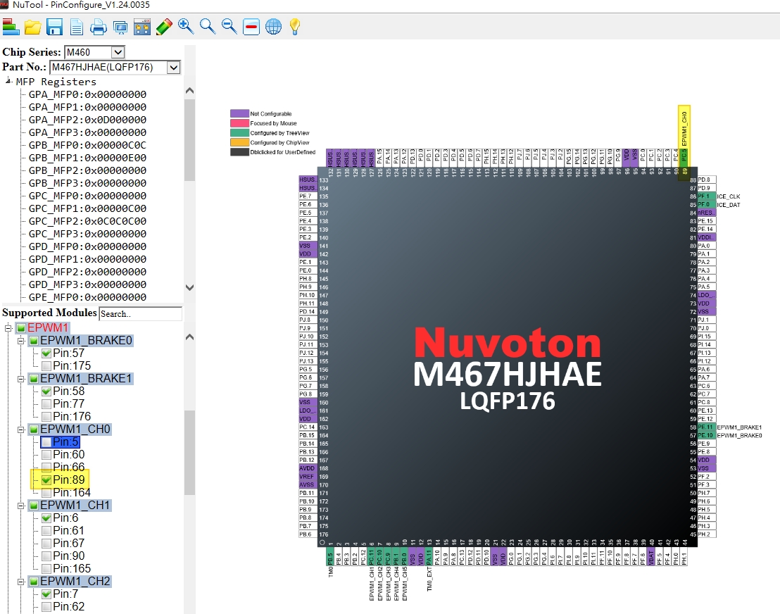
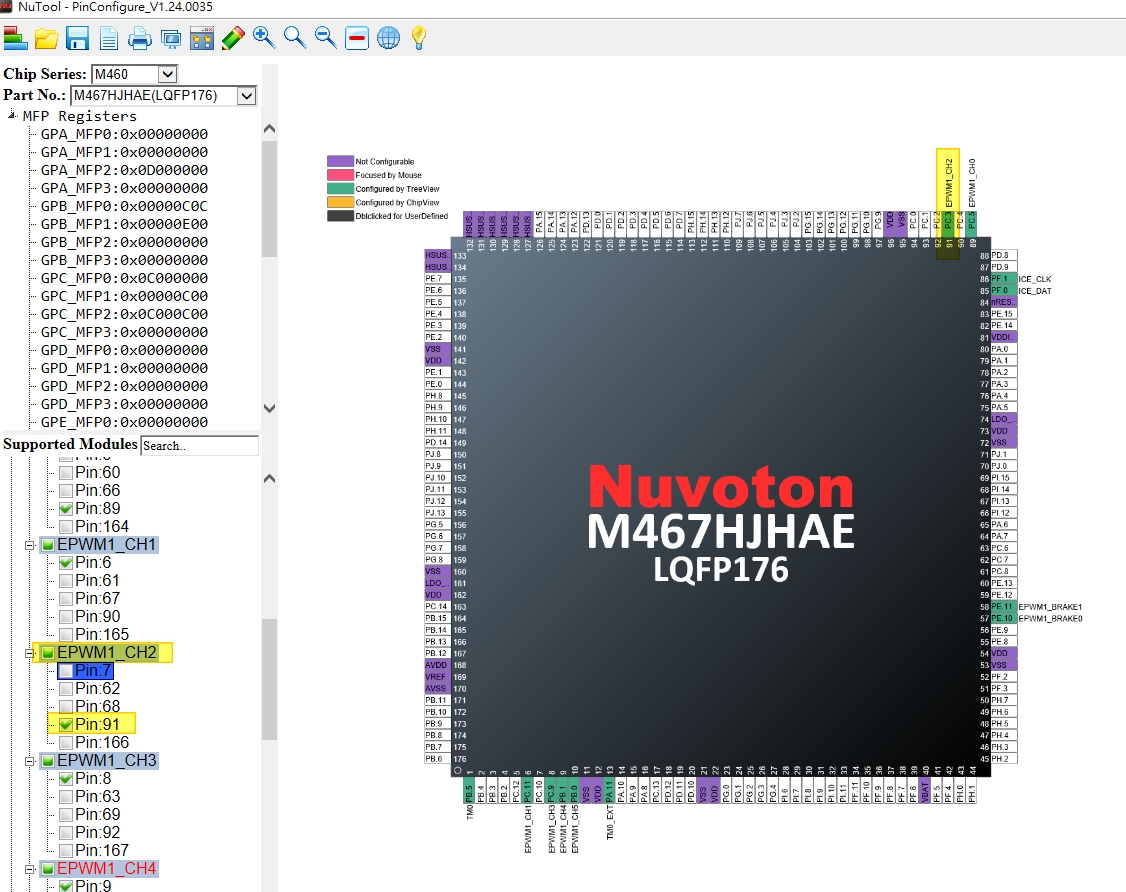
我是找 BSP 使用的 PWM PIN 角, 但還是用pinconfigure 看一下
所以根據上圖以及BSP ,
PWM1 的 Channel0
會發訊號 給
PWM1 的 Channel2
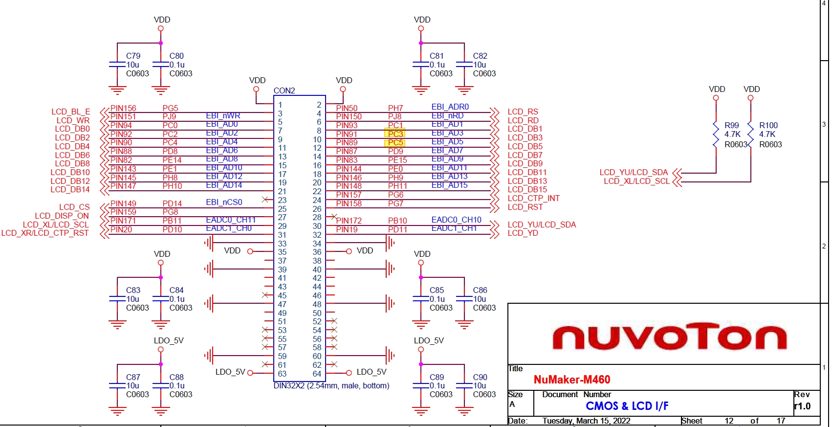
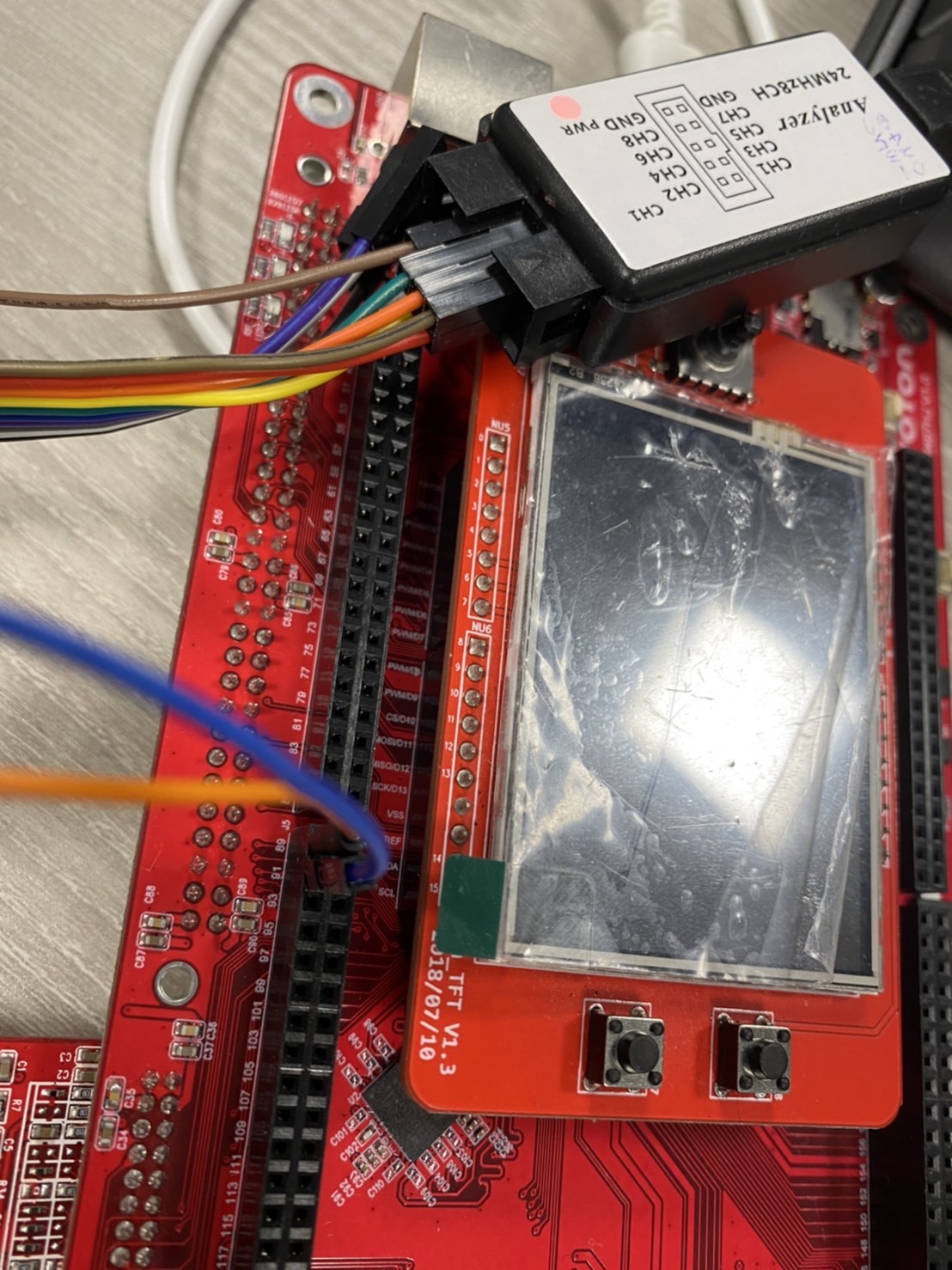
查看開發版的電路圖 是哪兩根PIN
EPWM_Capture BSP 的 console
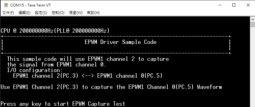
量測邏輯分析儀
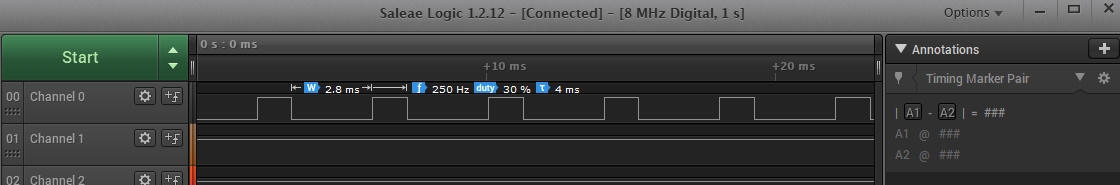

EPWM1 的 channel0 發 250 Hz pwm 訊號 30% duty
/**************************************************************************//**
 * @file     main.c
 * @version  V3.00
 * @brief    Capture the EPWM1 Channel 0 waveform by EPWM1 Channel 2.
 *
 * @copyright SPDX-License-Identifier: Apache-2.0
 * @copyright Copyright (C) 2021 Nuvoton Technology Corp. All rights reserved.
 ******************************************************************************/
#include <stdio.h>
#include "NuMicro.h"

/*---------------------------------------------------------------------------------------------------------*/
/* Macro, type and constant definitions                                                                    */
/*---------------------------------------------------------------------------------------------------------*/


/*---------------------------------------------------------------------------------------------------------*/
/* Global variables                                                                                        */
/*---------------------------------------------------------------------------------------------------------*/
void CalPeriodTime(EPWM_T *EPWM, uint32_t u32Ch);
void SYS_Init(void);
void UART0_Init(void);
/*--------------------------------------------------------------------------------------*/
/* Capture function to calculate the input waveform information                         */
/* au32Count[4] : Keep the internal counter value when input signal rising / falling     */
/*               happens                                                                */
/*                                                                                      */
/* time    A    B     C     D                                                           */
/*           ___   ___   ___   ___   ___   ___   ___   ___                              */
/*      ____|   |_|   |_|   |_|   |_|   |_|   |_|   |_|   |_____                        */
/* index              0 1   2 3                                                         */
/*                                                                                      */
/* The capture internal counter down count from 0x10000, and reload to 0x10000 after    */
/* input signal falling happens (Time B/C/D)                                            */
/*--------------------------------------------------------------------------------------*/
void CalPeriodTime(EPWM_T *EPWM, uint32_t u32Ch)
{
    uint16_t au16Count[4];
    uint32_t u32i;
    uint16_t u16RisingTime, u16FallingTime, u16HighPeriod, u16LowPeriod, u16TotalPeriod;

    /* Clear Capture Falling Indicator (Time A) */
    EPWM_ClearCaptureIntFlag(EPWM, u32Ch, EPWM_CAPTURE_INT_FALLING_LATCH);

    /* Wait for Capture Falling Indicator  */
    while((EPWM1->CAPIF & EPWM_CAPIF_CFLIF2_Msk) == 0);

    /* Clear Capture Falling Indicator (Time B)*/
    EPWM_ClearCaptureIntFlag(EPWM, u32Ch, EPWM_CAPTURE_INT_FALLING_LATCH);

    u32i = 0;

    while(u32i < 4)
    {
        /* Wait for Capture Falling Indicator */
        while(EPWM_GetCaptureIntFlag(EPWM, u32Ch) < 2);

        /* Clear Capture Falling and Rising Indicator */
        EPWM_ClearCaptureIntFlag(EPWM, u32Ch, EPWM_CAPTURE_INT_FALLING_LATCH | EPWM_CAPTURE_INT_RISING_LATCH);

        /* Get Capture Falling Latch Counter Data */
        au16Count[u32i++] = (uint16_t)EPWM_GET_CAPTURE_FALLING_DATA(EPWM, u32Ch);

        /* Wait for Capture Rising Indicator */
        while(EPWM_GetCaptureIntFlag(EPWM, u32Ch) < 2);

        /* Clear Capture Rising Indicator */
        EPWM_ClearCaptureIntFlag(EPWM, u32Ch, EPWM_CAPTURE_INT_RISING_LATCH);

        /* Get Capture Rising Latch Counter Data */
        au16Count[u32i++] = (uint16_t)EPWM_GET_CAPTURE_RISING_DATA(EPWM, u32Ch);
    }

    u16RisingTime = au16Count[1];

    u16FallingTime = au16Count[0];

    u16HighPeriod = au16Count[1] - au16Count[2];

    u16LowPeriod = (uint16_t)(0x10000 - au16Count[1]);

    u16TotalPeriod = (uint16_t)(0x10000 - au16Count[2]);

    printf("\nEPWM generate: \nHigh Period=17141 ~ 17143, Low Period=39999 ~ 40001, Total Period=57141 ~ 57143\n");
    printf("\nCapture Result: Rising Time = %d, Falling Time = %d \nHigh Period = %d, Low Period = %d, Total Period = %d.\n\n",
           u16RisingTime, u16FallingTime, u16HighPeriod, u16LowPeriod, u16TotalPeriod);
    if((u16HighPeriod < 17141) || (u16HighPeriod > 17143) || (u16LowPeriod < 39999) || (u16LowPeriod > 40001) || (u16TotalPeriod < 57141) || (u16TotalPeriod > 57143))
        printf("Capture Test Fail!!\n");
    else
        printf("Capture Test Pass!!\n");
}

void SYS_Init(void)
{

    /* Set PF multi-function pins for XT1_OUT(PF.2) and XT1_IN(PF.3) */
    SET_XT1_OUT_PF2();
    SET_XT1_IN_PF3();

    /*---------------------------------------------------------------------------------------------------------*/
    /* Init System Clock                                                                                       */
    /*---------------------------------------------------------------------------------------------------------*/

    /* Enable HIRC and HXT clock */
    CLK_EnableXtalRC(CLK_PWRCTL_HIRCEN_Msk | CLK_PWRCTL_HXTEN_Msk);

    /* Wait for HIRC and HXT clock ready */
    CLK_WaitClockReady(CLK_STATUS_HIRCSTB_Msk | CLK_STATUS_HXTSTB_Msk);

    /* Set PCLK0 and PCLK1 to HCLK/2 */
    CLK->PCLKDIV = (CLK_PCLKDIV_APB0DIV_DIV2 | CLK_PCLKDIV_APB1DIV_DIV2);

    /* Set core clock to 200MHz */
    CLK_SetCoreClock(200000000);

    /* Enable all GPIO clock */
    CLK->AHBCLK0 |= CLK_AHBCLK0_GPACKEN_Msk | CLK_AHBCLK0_GPBCKEN_Msk | CLK_AHBCLK0_GPCCKEN_Msk | CLK_AHBCLK0_GPDCKEN_Msk |
                    CLK_AHBCLK0_GPECKEN_Msk | CLK_AHBCLK0_GPFCKEN_Msk | CLK_AHBCLK0_GPGCKEN_Msk | CLK_AHBCLK0_GPHCKEN_Msk;
    CLK->AHBCLK1 |= CLK_AHBCLK1_GPICKEN_Msk | CLK_AHBCLK1_GPJCKEN_Msk;

    /* Enable UART0 module clock */
    CLK_EnableModuleClock(UART0_MODULE);

    /* Select UART0 module clock source as HIRC and UART0 module clock divider as 1 */
    CLK_SetModuleClock(UART0_MODULE, CLK_CLKSEL1_UART0SEL_HIRC, CLK_CLKDIV0_UART0(1));

    /* Enable EPWM1 module clock */
    CLK_EnableModuleClock(EPWM1_MODULE);

    /* Select EPWM1 module clock source */
    CLK_SetModuleClock(EPWM1_MODULE, CLK_CLKSEL2_EPWM1SEL_PCLK1, 0);


    /*---------------------------------------------------------------------------------------------------------*/
    /* Init I/O Multi-function                                                                                 */
    /*---------------------------------------------------------------------------------------------------------*/

    /* Set multi-function pins for UART0 RXD and TXD */
    SET_UART0_RXD_PB12();
    SET_UART0_TXD_PB13();

    /* Set multi-function pin for EPWM */
    SET_EPWM1_CH0_PC5();
    SET_EPWM1_CH2_PC3();

}

void UART0_Init(void)
{
    /*---------------------------------------------------------------------------------------------------------*/
    /* Init UART                                                                                               */
    /*---------------------------------------------------------------------------------------------------------*/

    /* Configure UART0 and set UART0 baud rate */
    UART_Open(UART0, 115200);
}


/*---------------------------------------------------------------------------------------------------------*/
/*  Main Function                                                                                          */
/*---------------------------------------------------------------------------------------------------------*/
int32_t main(void)
{
    /* Init System, IP clock and multi-function I/O
       In the end of SYS_Init() will issue SYS_LockReg()
       to lock protected register. If user want to write
       protected register, please issue SYS_UnlockReg()
       to unlock protected register if necessary */

    /* Unlock protected registers */
    SYS_UnlockReg();

    /* Init System, IP clock and multi-function I/O */
    SYS_Init();

    /* Lock protected registers */
    SYS_LockReg();

    /* Init UART to 115200-8n1 for print message */
    UART0_Init();

    printf("\n\nCPU @ %dHz(PLL@ %dHz)\n", SystemCoreClock, PllClock);
    printf("+------------------------------------------------------------------------+\n");
    printf("|                          EPWM Driver Sample Code                       |\n");
    printf("|                                                                        |\n");
    printf("+------------------------------------------------------------------------+\n");
    printf("  This sample code will use EPWM1 channel 2 to capture\n  the signal from EPWM1 channel 0.\n");
    printf("  I/O configuration:\n");
    printf("    EPWM1 channel 2(PC.3) <--> EPWM1 channel 0(PC.5)\n\n");
    printf("Use EPWM1 Channel 2(PC.3) to capture the EPWM1 Channel 0(PC.5) Waveform\n");

    while(1)
    {
        printf("\n\nPress any key to start EPWM Capture Test\n");
        getchar();

        /*--------------------------------------------------------------------------------------*/
        /* Set the EPWM1 Channel 0 as EPWM output function.                                     */
        /*--------------------------------------------------------------------------------------*/

        /* Assume EPWM output frequency is 250Hz and duty ratio is 30%, user can calculate EPWM settings by follows.(up counter type)
           duty ratio = (CMR)/(CNR+1)
           cycle time = CNR+1
           High level = CMR
           EPWM clock source frequency = PLL/2 = 100000000
           (CNR+1) = EPWM clock source frequency/prescaler/EPWM output frequency
                   = 100000000/7/250 = 57142
           (Note: CNR is 16 bits, so if calculated value is larger than 65536, user should increase prescale value.)
           CNR = 57141
           duty ratio = 30% ==> (CMR)/(CNR+1) = 30%
           CMR = 17142
           Prescale value is 6 : prescaler= 7
        */

        /* Set EPWM1 channel 0 output configuration */
        EPWM_ConfigOutputChannel(EPWM1, 0, 250, 30);

        /* Enable EPWM Output path for EPWM1 channel 0 */
        EPWM_EnableOutput(EPWM1, EPWM_CH_0_MASK);

        /* Enable Timer for EPWM1 channel 0 */
        EPWM_Start(EPWM1, EPWM_CH_0_MASK);

        /*--------------------------------------------------------------------------------------*/
        /* Set the EPWM1 channel 2 for capture function                                         */
        /*--------------------------------------------------------------------------------------*/

        /* If input minimum frequency is 250Hz, user can calculate capture settings by follows.
           Capture clock source frequency = PLL = 100000000 in the sample code.
           (CNR+1) = Capture clock source frequency/prescaler/minimum input frequency
                   = 100000000/7/250 = 57142
           (Note: CNR is 16 bits, so if calculated value is larger than 65536, user should increase prescale value.)
           CNR = 0xFFFF
           (Note: In capture mode, user should set CNR to 0xFFFF to increase capture frequency range.)

           Capture unit time = 1/Capture clock source frequency/prescaler
           70 ns = 1/100000000/7
        */

        /* Set EPWM1 channel 2 capture configuration */
        EPWM_ConfigCaptureChannel(EPWM1, 2, 70, 0);

        /* Enable Timer for EPWM1 channel 2 */
        EPWM_Start(EPWM1, EPWM_CH_2_MASK);

        /* Enable Capture Function for EPWM1 channel 2 */
        EPWM_EnableCapture(EPWM1, EPWM_CH_2_MASK);

        /* Enable falling capture reload */
        EPWM1->CAPCTL |= EPWM_CAPCTL_FCRLDEN2_Msk;

        /* Wait until EPWM1 channel 2 Timer start to count */
        while((EPWM1->CNT[2]) == 0);

        /* Capture the Input Waveform Data */
        CalPeriodTime(EPWM1, 2);
        /*------------------------------------------------------------------------------------------------------------*/
        /* Stop EPWM1 channel 0 (Recommended procedure method 1)                                                      */
        /* Set EPWM Timer loaded value(Period) as 0. When EPWM internal counter(CNT) reaches to 0, disable EPWM Timer */
        /*------------------------------------------------------------------------------------------------------------*/

        /* Set EPWM1 channel 0 loaded value as 0 */
        EPWM_Stop(EPWM1, EPWM_CH_0_MASK);

        /* Wait until EPWM1 channel 0 Timer Stop */
        while((EPWM1->CNT[0] & EPWM_CNT0_CNT_Msk) != 0);

        /* Disable Timer for EPWM1 channel 0 */
        EPWM_ForceStop(EPWM1, EPWM_CH_0_MASK);

        /* Disable EPWM Output path for EPWM1 channel 0 */
        EPWM_DisableOutput(EPWM1, EPWM_CH_0_MASK);

        /*------------------------------------------------------------------------------------------------------------*/
        /* Stop EPWM1 channel 2 (Recommended procedure method 1)                                                      */
        /* Set EPWM Timer loaded value(Period) as 0. When EPWM internal counter(CNT) reaches to 0, disable EPWM Timer */
        /*------------------------------------------------------------------------------------------------------------*/

        /* Set loaded value as 0 for EPWM1 channel 2 */
        EPWM_Stop(EPWM1, EPWM_CH_2_MASK);

        /* Wait until EPWM1 channel 2 current counter reach to 0 */
        while((EPWM1->CNT[2] & EPWM_CNT2_CNT_Msk) != 0);

        /* Disable Timer for EPWM1 channel 2 */
        EPWM_ForceStop(EPWM1, EPWM_CH_2_MASK);

        /* Disable Capture Function and Capture Input path for  EPWM1 channel 2*/
        EPWM_DisableCapture(EPWM1, EPWM_CH_2_MASK);

        /* Clear Capture Interrupt flag for EPWM1 channel 2 */
        EPWM_ClearCaptureIntFlag(EPWM1, 2, EPWM_CAPTURE_INT_FALLING_LATCH);
    }
}

/*** (C) COPYRIGHT 2021 Nuvoton Technology Corp. ***/