說明文件
 comments powered by Disqus
Timer Delay 說明 (by M460)
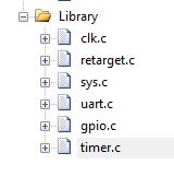
加入Timer的Driver
在 SYS_Init() 時 ,加入TMR0 的 clock source
    /*---------------------------------------------------------------------------------------------------------*/
    /* Initialization for sample code                                                                          */
    /*---------------------------------------------------------------------------------------------------------*/
    /* Enable TIMER module clock */
    CLK_EnableModuleClock(TMR0_MODULE);

    /* Select TIMER clock source */
    CLK_SetModuleClock(TMR0_MODULE, CLK_CLKSEL1_TMR0SEL_HIRC, 0);
在 SYS_Init() 時 ,加入TMR0 的 clock source
    while(1) {
        PH4 = 1;
        TIMER_Delay(TIMER0, 1000000);
        PH4 = 0;
        TIMER_Delay(TIMER0, 1000000);
    }
邏輯分析儀量測 LED 訊號
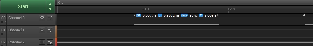
用 Timer0 控制 LED 1秒亮 1秒滅
/**************************************************************************//**
 * @file     main.c
 * @version  V3.00
 * @brief    Transmit and receive data from PC terminal through RS232 interface.
 *
 * @copyright SPDX-License-Identifier: Apache-2.0
 * @copyright Copyright (C) 2021 Nuvoton Technology Corp. All rights reserved.
 ******************************************************************************/
#include <stdio.h>
#include "NuMicro.h"


#define RXBUFSIZE   1024

/*---------------------------------------------------------------------------------------------------------*/
/* Global variables                                                                                        */
/*---------------------------------------------------------------------------------------------------------*/
static uint8_t g_u8RecData[RXBUFSIZE]  = {0};

static volatile uint32_t g_u32comRbytes = 0;
static volatile uint32_t g_u32comRhead  = 0;
static volatile uint32_t g_u32comRtail  = 0;
static volatile int32_t g_i32Wait       = TRUE;

/*---------------------------------------------------------------------------------------------------------*/
/* Define functions prototype                                                                              */
/*---------------------------------------------------------------------------------------------------------*/
int32_t main(void);
void UART_TEST_HANDLE(void);
void UART_FunctionTest(void);

void SYS_Init(void);
void UART0_Init(void);
void UART0_IRQHandler(void);


void SYS_Init(void)
{

    /*---------------------------------------------------------------------------------------------------------*/
    /* Init System Clock                                                                                       */
    /*---------------------------------------------------------------------------------------------------------*/

    /* Set PCLK0 and PCLK1 to HCLK/2 */
    CLK->PCLKDIV = (CLK_PCLKDIV_APB0DIV_DIV2 | CLK_PCLKDIV_APB1DIV_DIV2);

    /* Set core clock to 200MHz */
    CLK_SetCoreClock(200000000);

    /* Enable all GPIO clock */
    CLK->AHBCLK0 |= CLK_AHBCLK0_GPACKEN_Msk | CLK_AHBCLK0_GPBCKEN_Msk | CLK_AHBCLK0_GPCCKEN_Msk | CLK_AHBCLK0_GPDCKEN_Msk |
                    CLK_AHBCLK0_GPECKEN_Msk | CLK_AHBCLK0_GPFCKEN_Msk | CLK_AHBCLK0_GPGCKEN_Msk | CLK_AHBCLK0_GPHCKEN_Msk;
    CLK->AHBCLK1 |= CLK_AHBCLK1_GPICKEN_Msk | CLK_AHBCLK1_GPJCKEN_Msk;

    /* Enable UART module clock */
    CLK_EnableModuleClock(UART0_MODULE);
    CLK_EnableModuleClock(UART1_MODULE);

    /* Select UART module clock source and UART module clock divider */
    CLK_SetModuleClock(UART0_MODULE, CLK_CLKSEL1_UART0SEL_HIRC, CLK_CLKDIV0_UART0(1));
    CLK_SetModuleClock(UART1_MODULE, CLK_CLKSEL1_UART1SEL_HIRC, CLK_CLKDIV0_UART1(1));

    /*---------------------------------------------------------------------------------------------------------*/
    /* Init I/O Multi-function                                                                                 */
    /*---------------------------------------------------------------------------------------------------------*/

    /* Set multi-function pins for UART0 RXD and TXD */
    SET_UART0_RXD_PB12();
    SET_UART0_TXD_PB13();


    /*---------------------------------------------------------------------------------------------------------*/
    /* Initialization for sample code                                                                          */
    /*---------------------------------------------------------------------------------------------------------*/
    /* Enable TIMER module clock */
    CLK_EnableModuleClock(TMR0_MODULE);

    /* Select TIMER clock source */
    CLK_SetModuleClock(TMR0_MODULE, CLK_CLKSEL1_TMR0SEL_HIRC, 0);

}


void UART0_Init(void)
{
    /*---------------------------------------------------------------------------------------------------------*/
    /* Init UART                                                                                               */
    /*---------------------------------------------------------------------------------------------------------*/
    /* Reset UART0 */
    SYS_ResetModule(UART0_RST);

    /* Configure UART0 and set UART0 baud rate */
    UART_Open(UART0, 115200);
}


/*---------------------------------------------------------------------------------------------------------*/
/*  Main Function                                                                                          */
/*---------------------------------------------------------------------------------------------------------*/
int32_t main(void)
{
    /* Unlock protected registers */
    SYS_UnlockReg();
    /* Init System, peripheral clock and multi-function I/O */
    SYS_Init();
    /* Lock protected registers */
    SYS_LockReg();
    /* Init UART0 for printf */
    UART0_Init();


    GPIO_SetMode(PH, BIT4, GPIO_MODE_OUTPUT);


    printf("test \n");


    while(1) {
        PH4 = 1;
        TIMER_Delay(TIMER0, 1000000);
        PH4 = 0;
        TIMER_Delay(TIMER0, 1000000);
    }

}

/*---------------------------------------------------------------------------------------------------------*/
/* ISR to handle UART Channel 0 interrupt event                                                            */
/*---------------------------------------------------------------------------------------------------------*/
void UART0_IRQHandler(void)
{
    UART_TEST_HANDLE();
}

/*---------------------------------------------------------------------------------------------------------*/
/* UART Callback function                                                                                  */
/*---------------------------------------------------------------------------------------------------------*/
void UART_TEST_HANDLE(void)
{
    uint8_t u8InChar = 0xFF;
    uint32_t u32IntSts = UART0->INTSTS;

    if(u32IntSts & UART_INTSTS_RDAINT_Msk)
    {
        printf("\nInput:");

        /* Get all the input characters */
        while(UART_IS_RX_READY(UART0))
        {
            /* Get the character from UART Buffer */
            u8InChar = (uint8_t)UART_READ(UART0);

            printf("%c ", u8InChar);

            if(u8InChar == '0')
            {
                g_i32Wait = FALSE;
            }

            /* Check if buffer full */
            if(g_u32comRbytes < RXBUFSIZE)
            {
                /* Enqueue the character */
                g_u8RecData[g_u32comRtail] = u8InChar;
                g_u32comRtail = (g_u32comRtail == (RXBUFSIZE - 1)) ? 0 : (g_u32comRtail + 1);
                g_u32comRbytes++;
            }
        }
        printf("\nTransmission Test:");

        /* Forces a write of all user-space buffered data for the given output */
        fflush(stdout);
    }

    if(u32IntSts & UART_INTSTS_THREINT_Msk)
    {
        uint32_t u32Tmp;
        u32Tmp = g_u32comRtail;
        if(g_u32comRhead != u32Tmp)
        {
            u8InChar = g_u8RecData[g_u32comRhead];
            while(UART_IS_TX_FULL(UART0));  /* Wait Tx is not full to transmit data */
            UART_WRITE(UART0, u8InChar);
            g_u32comRhead = (g_u32comRhead == (RXBUFSIZE - 1)) ? 0 : (g_u32comRhead + 1);
            g_u32comRbytes--;
        }
    }

    /* Handle transmission error */
    if(UART0->FIFOSTS & (UART_FIFOSTS_BIF_Msk | UART_FIFOSTS_FEF_Msk | UART_FIFOSTS_PEF_Msk | UART_FIFOSTS_RXOVIF_Msk))
    {
        UART0->FIFOSTS = (UART_FIFOSTS_BIF_Msk | UART_FIFOSTS_FEF_Msk | UART_FIFOSTS_PEF_Msk | UART_FIFOSTS_RXOVIF_Msk);
    }
}

/*---------------------------------------------------------------------------------------------------------*/
/*  UART Function Test                                                                                     */
/*---------------------------------------------------------------------------------------------------------*/
void UART_FunctionTest(void)
{
    printf("+-----------------------------------------------------------+\n");
    printf("|  UART Function Test                                       |\n");
    printf("+-----------------------------------------------------------+\n");
    printf("|  Description :                                            |\n");
    printf("|    The sample code will print input char on terminal      |\n");
    printf("|    Please enter any to start     (Press '0' to exit)      |\n");
    printf("+-----------------------------------------------------------+\n");

    /*
        Using a RS232 cable to connect UART0 and PC.
        UART0 is set to debug port. UART0 is enable RDA interrupt.
        When inputting char to terminal screen, RDA interrupt will happen and
        UART0 will print the received char on screen.
    */

    /* Enable UART RDA and THRE interrupt */
    NVIC_EnableIRQ(UART0_IRQn);
    UART_EnableInt(UART0, (UART_INTEN_RDAIEN_Msk | UART_INTEN_THREIEN_Msk));
    while(g_i32Wait);

    /* Disable UART RDA and THRE interrupt */
    NVIC_DisableIRQ(UART0_IRQn);
    UART_DisableInt(UART0, (UART_INTEN_RDAIEN_Msk | UART_INTEN_THREIEN_Msk));
    g_i32Wait = TRUE;

}